This is a puzzle that requires two people to work together. It consists of two separate devices that are placed far from each other, for example in separate rooms. The objective is to raise the anchor of the pirate ship.
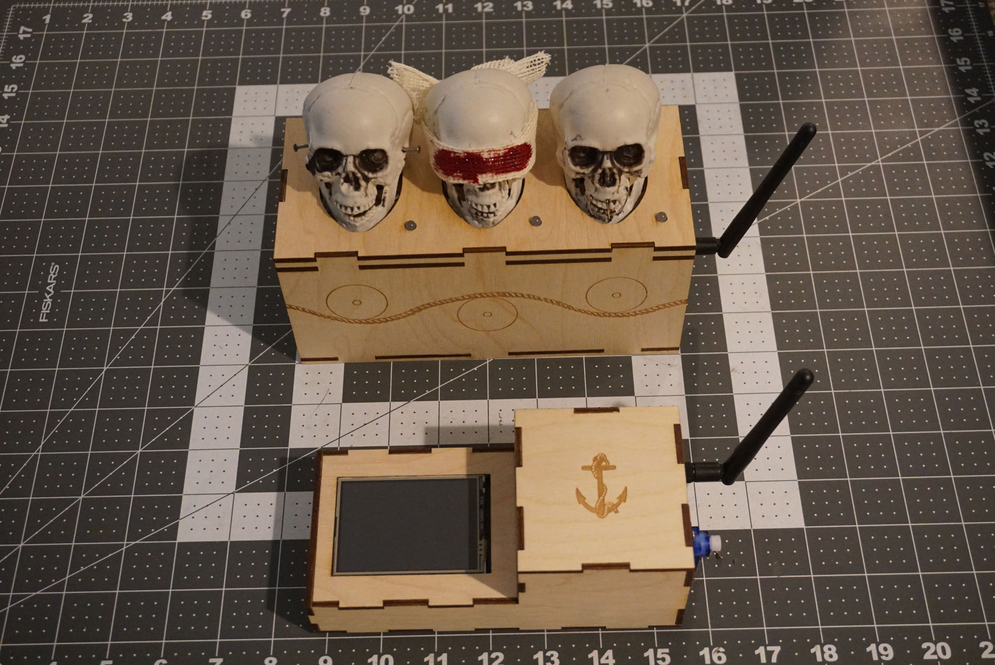
The first device – the “master” shows a sequence of 3 skull icons in some order – “see no evil”, “hear no evil” and “speak no evil”. One player has to look at them and has to relay the sequence to the second player. 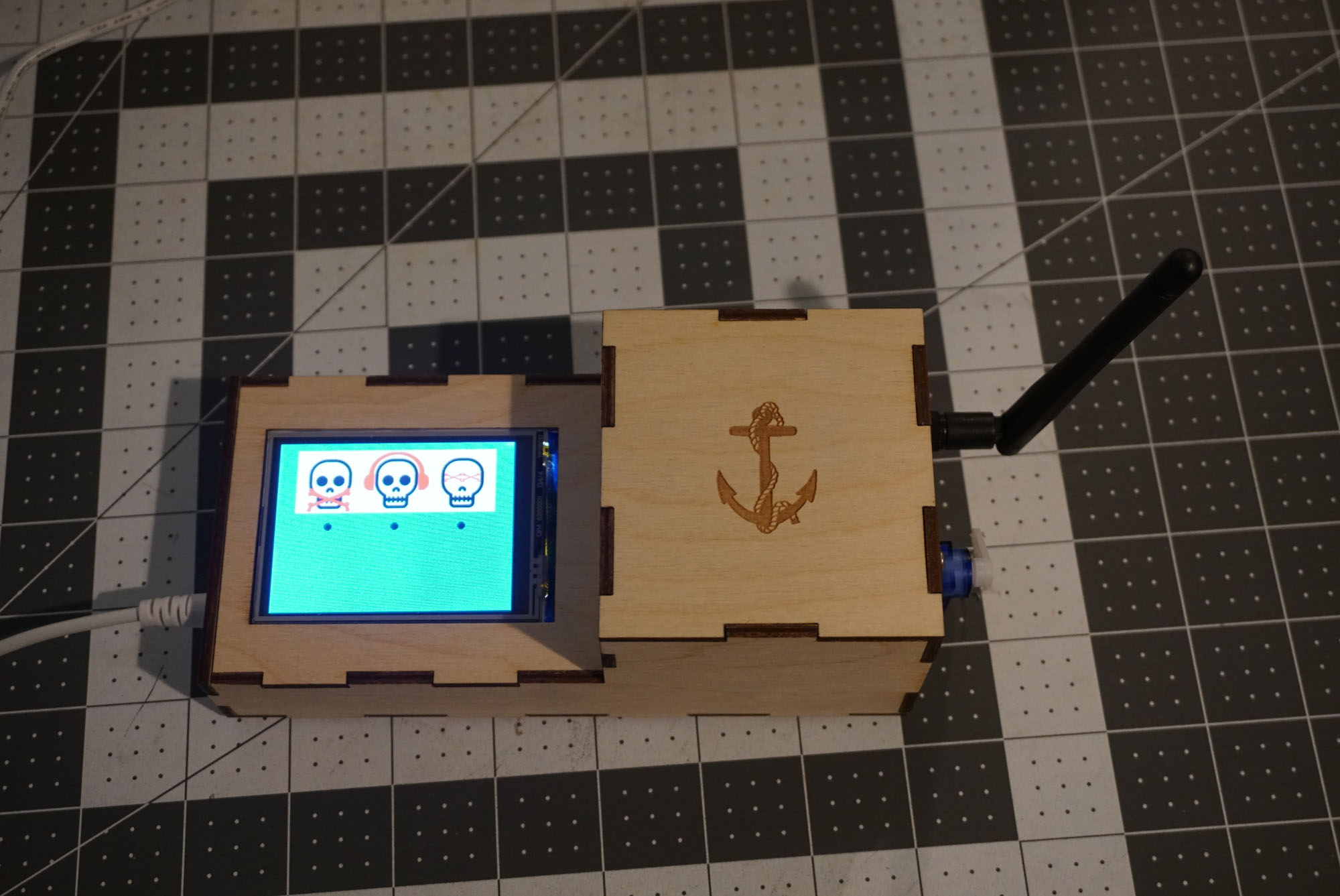
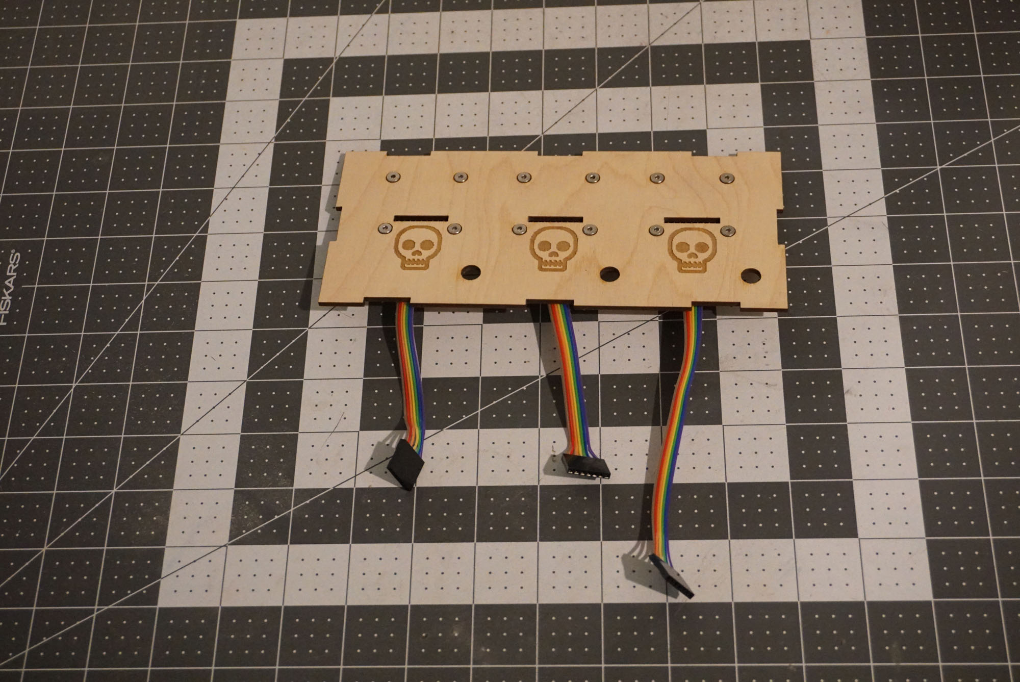
The second device – the “slave” has placements for 3 skulls that need to be arranged in the right order.
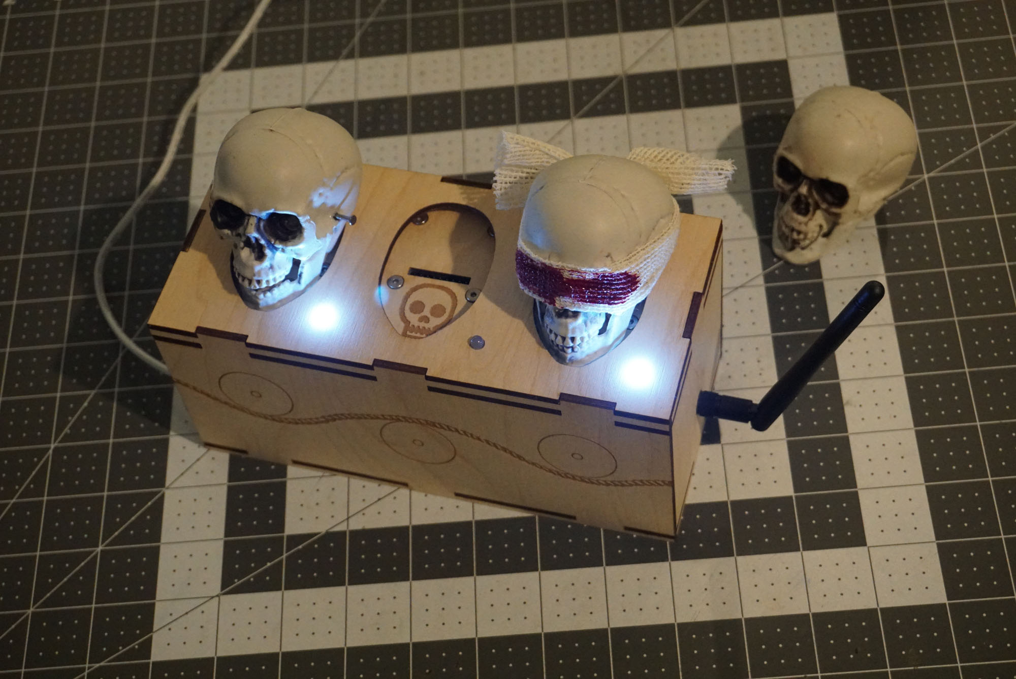
A light on the slave and a white dot on the master’s screen indicate that a skull was successfully placed (but not necessarily in the correct slot).
After each successful sequence, the anchor is raised a little bit and the skull order is randomized. It takes 5 steps to complete the puzzle and receive the final message. An incorrect sequence resets the puzzle.
Make It
Here are the essential parts you will need for the devices
* 2x Arduino Mega: https://www.amazon.com/gp/product/B01H4ZDYCE
For the slave device it should be possible to use Arduino Uno instead of the Mega, to save on size and cost. I believe it has enough pins to do the job. I used the Mega because that’s what I had laying around.
The master needs a Mega because the LCD screen doesn’t leave any free pins on the Uno. Also, the bitmaps for the skull images require lots of ROM (this can be improved by using procedural images or a palette instead of full 16-bit bitmaps)
* 2x NRF24L01 radio module: https://www.amazon.com/gp/product/B06WLH4ZG6
* 2x 3.3V voltage regulator for the NRF24L01: https://www.amazon.com/gp/product/B072BLN8SZ
* 3x MFRC5522 NFC reader: https://www.amazon.com/gp/product/B072V16RC4
I prefer these over the standard Arduino RFID modules because they are more compact and support 3.3V and 5V power. They can be hard to find though.
* 3x NFC stickers: https://www.amazon.com/gp/product/B01FR6M8SS
* Arduino LCD touch screen: https://www.amazon.com/gp/product/B01EUVJYME
* Prototype board for Arduino Mega: https://www.amazon.com/gp/product/B071JDRGGR
A prototype board is not strictly required but makes for a neater installation.
Additional materials:
* Dupont connectors, ribbon cables and a crimping tool for them
* M3 screws and plastic standoffs for mounting the Arduino board
The Master
The master device is very straight-forward from hardware point of view. It has one Arduino Mega board with the LCD shield attached directly to it and one radio module with a voltage regulator.
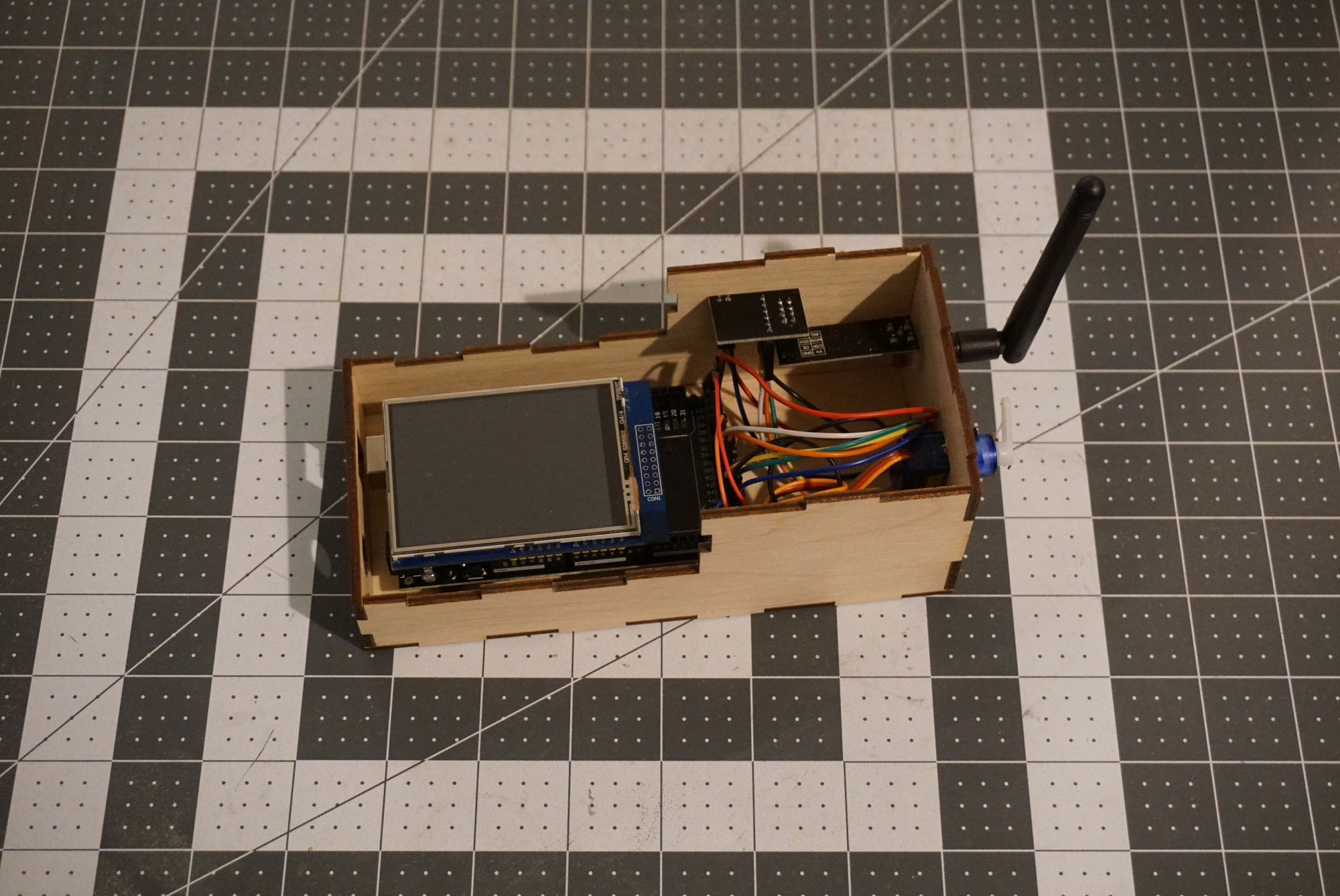
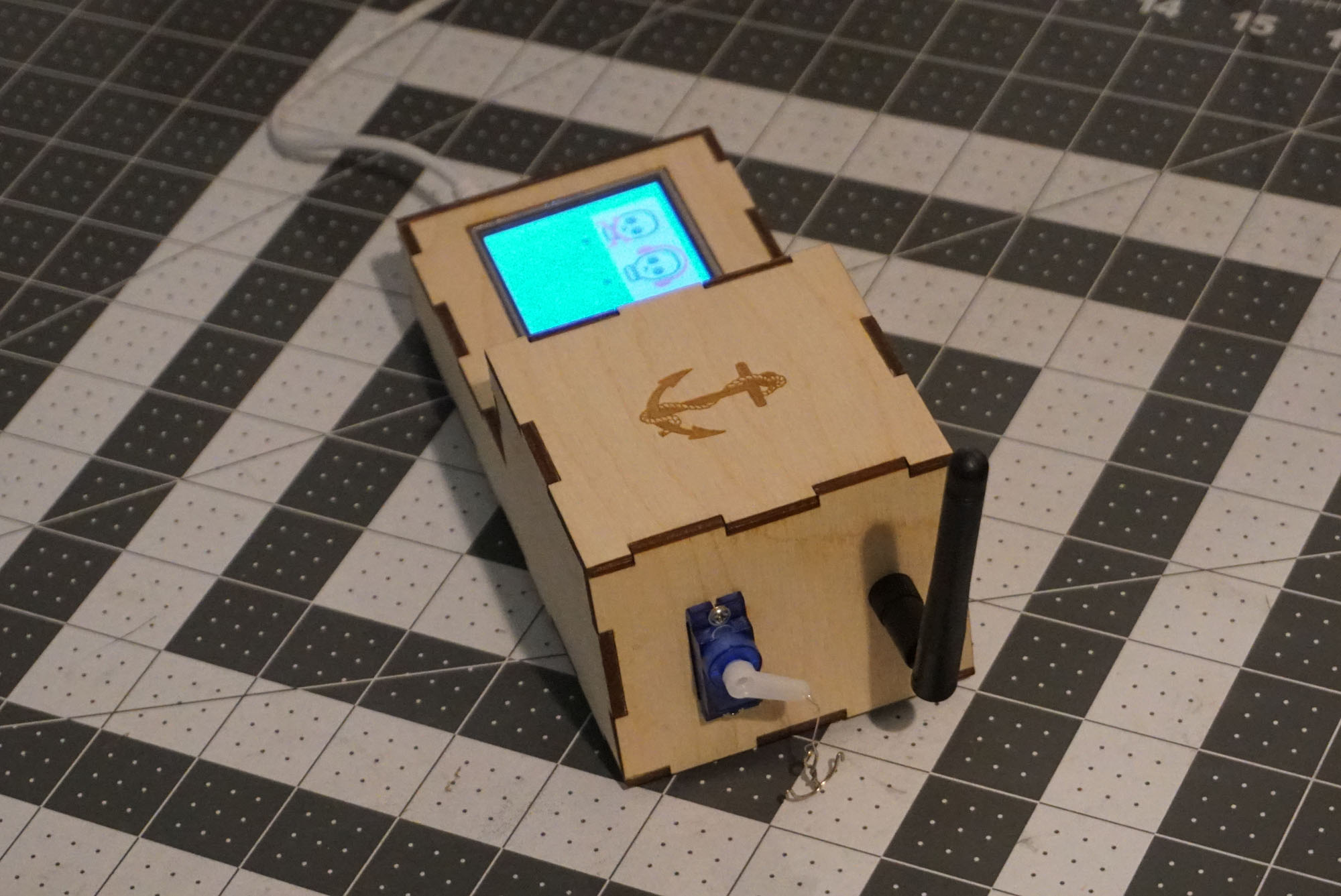
It also has a small servo on the side to raise the anchor, made from a paper clip and a piece of string.
The software is the more complex component. First it waits for the player to press the “Raise Anchor” button, and when the button is pressed it shows a prompt to send somebody to the location of the slave device. Then the software generates random skull sequences and listens for radio signal from the slave device. Once the correct sequence is detected, the servo raises the anchor. After 5 successful steps the screen shows the final message.
Download source code and SVG designs for the master: skull_master.zip
The box designs assume 3mm plywood. Some of the holes have concentric circles around them with different colors. They are intended to be etched with varying laser power, to create a conical hole for the screw heads and for the antenna.
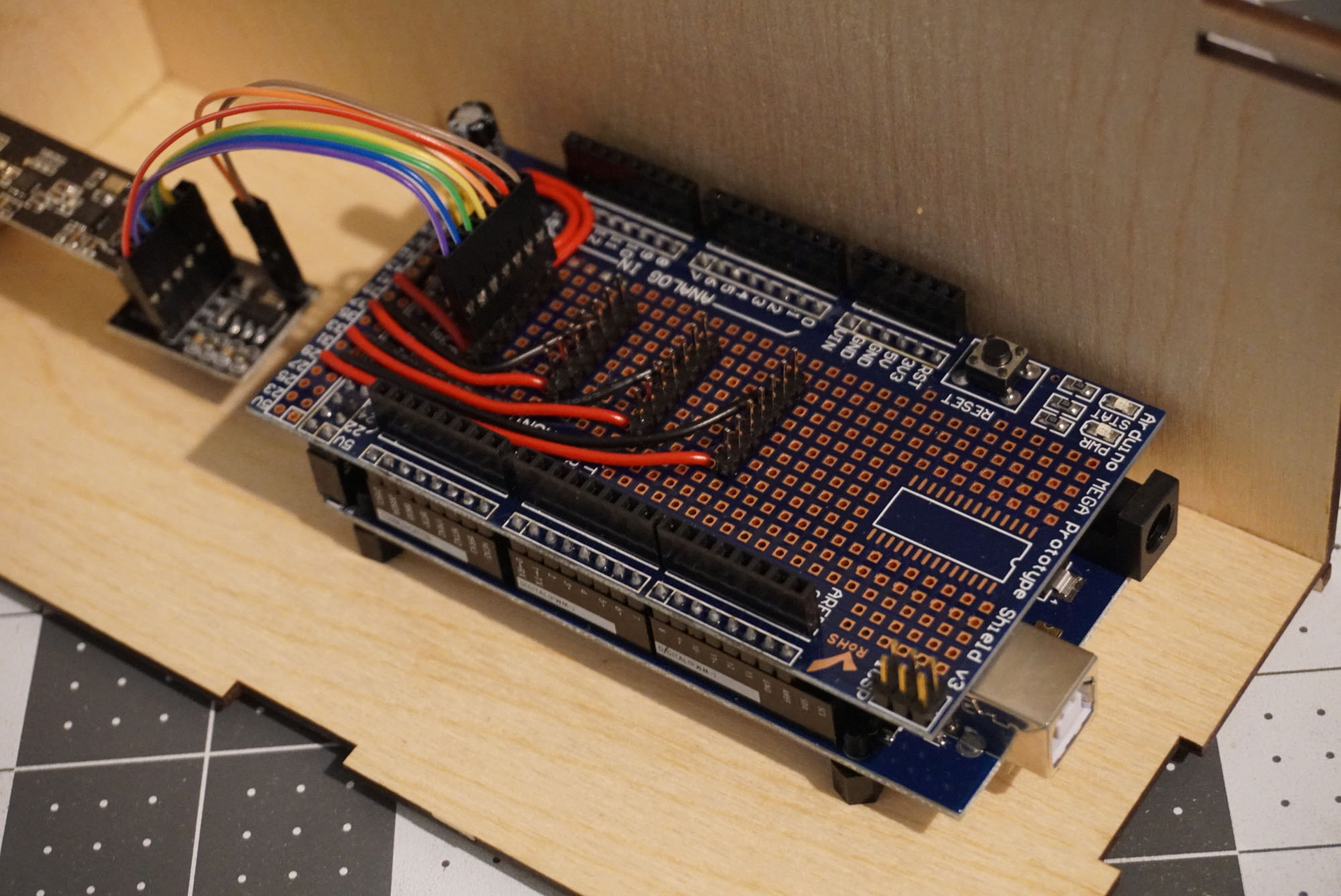
The Slave
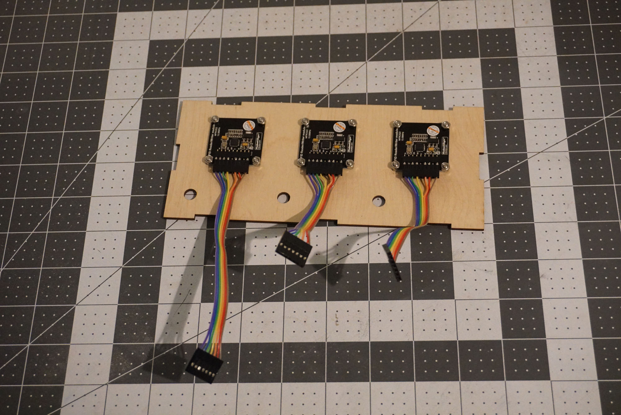
The slave device has an Arduino board, a radio module and the 3 NFC sensors. 3 LEDs illuminate when a skull is detected.
The sensors are attached to the top of the box using M3 screws and nuts. They are connected via ribbon cables to pins on the shield.
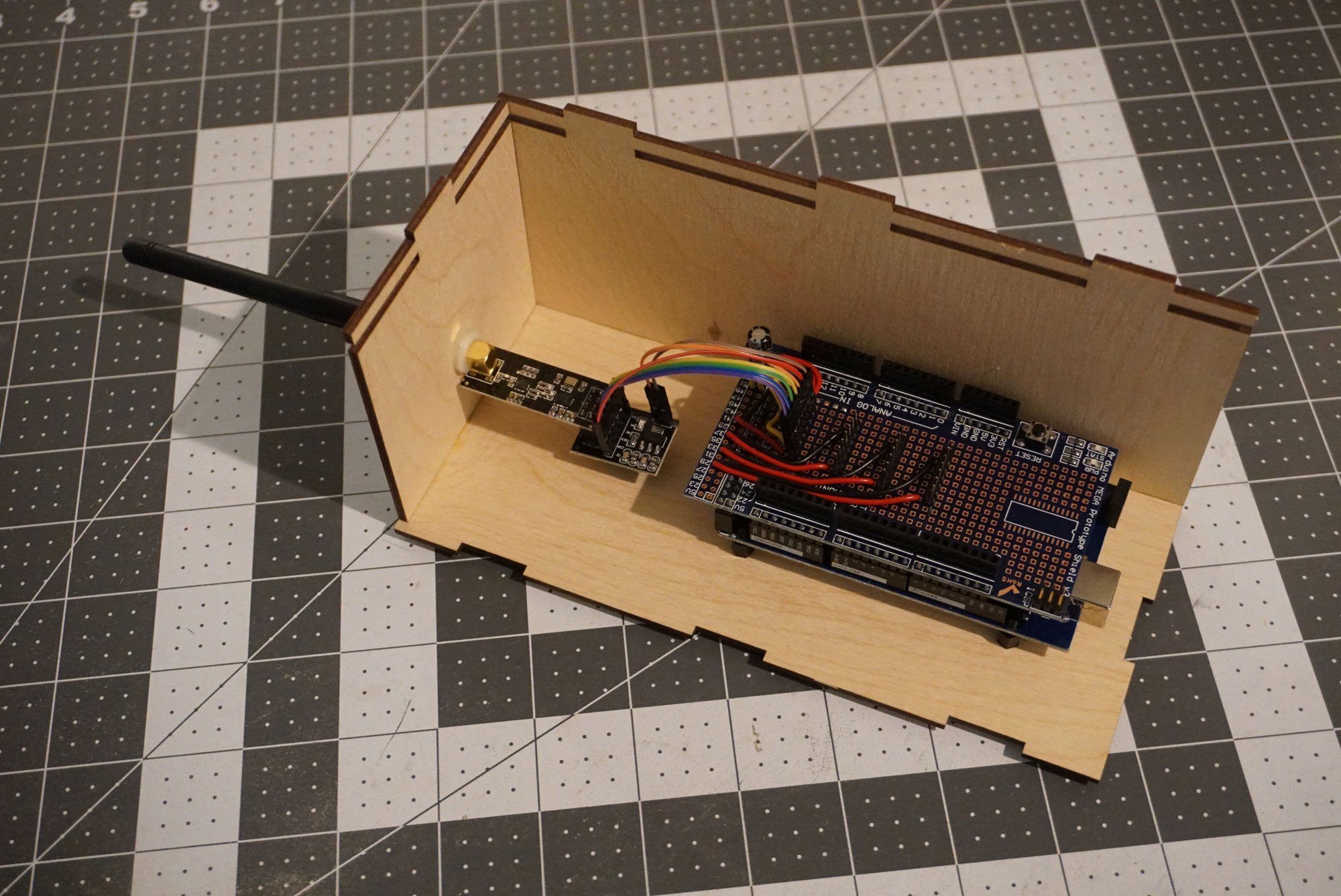
The shield itself is very simple. It is used to mount the 4 connectors for the SPI bus – one for the radio and 3 for the sensors.
The software for the slave device is quite simple. It reads the data from the NFC sensors and sends it periodically over the radio. The communication is only one way.
One problem I had with the slave device was that the radio was not working reliably while the NFC sensors were active. It is either that they draw too much power, or they produce some sort of interference. The solution that worked for me was to power down the sensors while the radio was sending data, by sending a LOW signal to the RST pin.
Assembly note: The antenna is held to the side of the box by the power of friction, so it is important to keep it tight. That can be tricky after the box is fully assembled. I glued small rectangles of plywood to the bottom of the box to keep the radio module from spinning while the antenna is being tightened from the outside.
This is not necessary for the master device, because the side of the box prevents the radio module from spinning. Keep this into account if you decide to redesign the master box.
Note on the range: During initial development, I was getting a range of a few feet using the low power mode for the radios. At the highest power setting I was able to get the devices to communicate between two floors in an office building, but not much further. Somebody with better understanding of electronics and radio communications may be able to get better results. If so, I’d like to know how.
Download source code and SVG designs for the slave: skull_slave.zip
Customize It
If you are making this puzzle, you will want to customize it for your needs.
Pick whatever props fit your theme – magic crystals, ancient runes, alien orbs, use your imagination. I myself got a bag of plastic skulls from Everything Party during their Halloween sale.
The shape and size of the slave box will depend mainly on the shape and size of the props that need to be arranged on top of it. It can be extended to support more objects. Each new slot requires 3 pins on the Arduino – one SS for the SPI interface, one RST for the sensor, and one for the LED. Also be mindful of the power requirements when adding sensors.
A possible improvement that I was considering but didn’t get to try, was to have the LED for each skull illuminate a piece of laser-etched acrylic placed under the skull to give it an eerie glow.
The master box can also be made more elaborate, just keep in mind that it is easiest if the LCD screen is mounted directly on the Arduino board. They can be separated apart but will need a lot of cables to connect them.